single flute
gundrills
Contact our Sales Representatives for more Details

Diameters from .0781” (1.983MM) TO 3.0” (228.6MM)
Lengths from 6” (152.4MM) – 140” (3,556MM)
The Single Flute Carbide Tipped Gundrill is manufactured as a 3-piece construction drill. The carbide head is brazed to an aircraft grade seamless tube, which is brazed to a driver.
Stock catalog gundrills are available for same day delivery and specials are quote specific. Holes less than .0781” (1.983mm) are manufactured as Solid Carbide construction.
CARBIDE HEAD
The Carbide Head is either extruded in sticks or preformed from a specific manufacturer to a designated size usually .020″ – .030″ larger than the finished diameter. Carbide selection is very critical; materials that are abrasive require different carbide composition than exotic types of materials. The proper combination of cobalt content and grain size make noticeable differences while machining. The carbide is then precision ground to size allowing for predetermined backtaper, relief depths, and contours.
OIL HOLE CONFIGURATIONS
Oil hole configurations play an important role in the gundrill selection process. Coolant systems that lack adequate pressure or volume would benefit from the single oil hole. The single orifice allows larger PSI with a smaller volume. Systems with ideal PSI and GPM should run either a Kidney (.3125” and under) or Dual (.3126” and up) oil holes for greater chip extraction due to the dub-off angles ability to break into the coolant orifice and allows more coolant to the cutting edge.

Backtaper & Relief depths
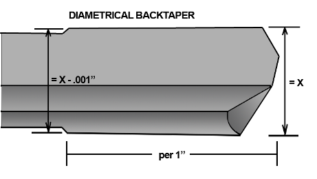
Backtaper is a linear reduction in the tool diameter allowing for clearance and minimal friction. Standard backtaper, .0008” – .0010” per inch, is generally used in steel applications where the heat generated by the bearing pads (contours) does not expand and contract the hole during the drilling process. Materials that heat and cool quickly such as aluminum, cast iron, etc. require increased backtaper to prevent the hole from closing in on the gundrill during the retract mode.

Relief depths
Relief depths are undercut and placed in specified locations to allow coolant to lubricate the bearing pads, therefore cooling the tool and obtaining optimal surface finishes. The depths of the reliefs are manufacturing standards and sometimes increased depending on the application.

Contours
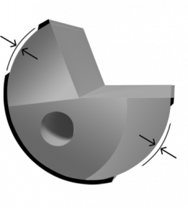
Contours, or bearing pads, are the actual surfaces that make contact with the material inside of the hole. This produces the burnishing effect which contributes to the balancing of the tool while in the cut. Various locations of these pads determine the amount of heat generated and allow for control of material distortion during the cut. Some pads like the R-1, are not 180 degrees apart (non micable) they allow for a much freer cutting tool.

Drivers
Drivers are manufactured from various materials depending on the hardness desired by a particular application. The spindles or tool holders determine the locking mechanisms prescribed for individual applications. The most common and standard is a two degree tapered flat in an under-cut centered in the driver and two tapered flats 90 degrees apart with a 2 degree taper. There are many variations as with machine stroke limitations; small diameter deep hole applications require longer drivers (extensions) to enable shorter tip and tube lengths. This allows for maximum surface feet per minute minimizing the whip factor. Many machine manufacturers dictate the drivers OD and lengths depending on their geographic location hence, metric or imperil.
Driver design is important because of the high speeds and pressures used in the gundrilling process. Maximizing the gundrill driver length improves rigidity and concentricity.
TECH SUPPORT
We have a dedicated staff of experts with over 85 years of combined experience to assist the customer with all of their special requirements. At the beginning phase of an engineering project, give us a call to discuss the process sequences required to avoid unnecessary problems in the future. If the customer is experiencing any gundrilling problems or has questions, they should contact our engineering staff for solutions.

