Deep Hole Drilling
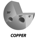
Nose Grinds


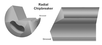
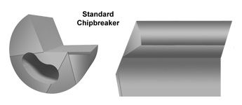
Chip Breakers
Determining Time To Re-grind
Contours
